
 English
 Español
Content
- 1 Definition and Working Principle of a Blower Impeller
- 2 What are the basic structural components of a blower impeller?
- 3 How to Determine if the Impeller Needs Rebalancing or Replacement?
- 4 How does the blower impeller work inside the blower?
- 5 How can CFD be used to optimize the impeller shape to improve efficiency during design?
Definition and Working Principle of a Blower Impeller
1. The Essence of the Impeller
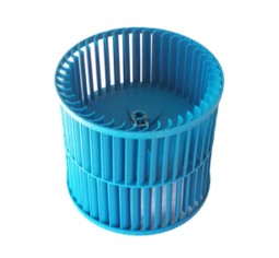
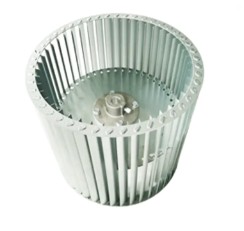
The blower impeller is the core rotating component of a blower, typically composed of several blades surrounding a central axis. Its main function is to convert the mechanical torque provided by the motor into the kinetic energy and pressure head of the gas, causing an orderly flow of gas.
2. Generation of Kinetic Energy and Pressure Head
When the impeller rotates at high speed, the blades apply centrifugal force to the incoming gas, accelerating it from the center to the outer edge of the impeller. The gas gains kinetic energy under the action of the blades, and then, in the volute or diffuser section, part of this kinetic energy is converted into static pressure head, achieving gas pressurization and delivery.
3. Common Impeller Types
Centrifugal Impeller: Gas is thrown radially towards the outer edge of the impeller. This is the most common structure and is suitable for high-flow, low-pressure ventilation systems.
Axial Impeller: Gas is propelled axially. It is often used in applications requiring higher airflow and limited space.
Hybrid impeller: Possesses both radial and axial flow characteristics, enabling higher efficiency under specific operating conditions.
What are the basic structural components of a blower impeller?
Basic structural components of a blower impeller:
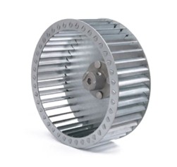
1. Hub and Wheel Plate
The hub is the central component of the impeller, responsible for bearing axial loads and transmitting torque to the blades. The wheel plate is the planar structure connecting the hub and blades, usually fixed by welding or riveting to ensure the rigidity and concentricity of the blades.
2. Blades
The shape, number, and angle of the blades directly determine the gas flow path and pressure head generation efficiency. Modern blades often use aerodynamically optimized arc or torsional shapes to reduce flow separation and eddy current losses.
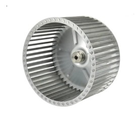
3. Shaft & Bearing
The shaft plate connects the motor shaft to the hub, and the bearings provide support and limit radial and axial displacement. High-speed impellers have extremely high requirements for bearing rigidity and lubrication, often using deep groove ball bearings or angular contact bearings.
4. Auxiliary Components
Volute: Collects and guides the gas discharged from the impeller, completing the conversion of kinetic energy to static pressure.
Coupling: Enables flexible coupling between the motor and the impeller, absorbing shock and axial displacement.
Seals and Protective Covers: Prevent gas leakage and protect internal components from external contamination.
How to Determine if the Impeller Needs Rebalancing or Replacement?
Impeller Balancing and Replacement Criteria
1. Vibration Monitoring
Vibration amplitude is monitored in real time using an accelerometer mounted on the base or bearing housing. The presence of 2–3 harmonics of the fundamental frequency or abnormal peaks in the vibration spectrum often indicates uneven impeller mass distribution or bearing wear.
2. Noise Changes
Impeller imbalance leads to asymmetrical airflow, generating additional aerodynamic noise. If the on-site noise level is more than 3dB higher than normal operation, further inspection of the impeller balancing is necessary.
3. Efficiency Decrease
If the airflow or pressure head decreases by more than 5% at the same rotational speed and inlet pressure, and cannot be restored to the design curve even by speed adjustment, it usually indicates that the impeller's aerodynamic performance is damaged, requiring recalibration or replacement.
4. Visual Inspection and Cracks
After periodic shutdowns, disassemble and inspect the impeller, observing for cracks, corrosion, or fatigue marks at the blade roots and hub welds. Any visible structural defects should be considered grounds for replacement.
How does the blower impeller work inside the blower?
Working Mechanism of the Impeller Inside the Blower
1. Airflow Inlet and Centrifugal Acceleration
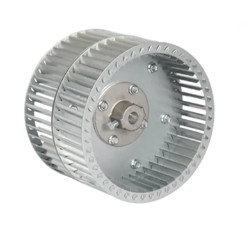
Gas first enters the inlet area at the center of the impeller (called the inlet), where it is accelerated by centrifugal force under the tilting angle of the blades, moving radially outwards.
2. Kinetic Energy Converted into Pressure Head
The kinetic energy generated by the high-speed rotation of the impeller increases the gas velocity under the action of centrifugal force. The gas then enters the diffuser section of the volute, where the geometry of the volute gradually reduces the flow velocity, converting kinetic energy into static pressure head, thus pressurizing the gas.
3. Flow Field Closure and Backflow Suppression
A well-designed volute can effectively collect the gas discharged from the impeller, preventing backflow or leakage. Backflow leads to energy loss and noise generation.
How can CFD be used to optimize the impeller shape to improve efficiency during design?
Application of CFD in Impeller Design Optimization
1. CFD Fundamentals and Model Building
Computational Fluid Dynamics (CFD) numerically simulates the three-dimensional flow field inside the impeller by solving the Navier-Stokes equations. The model typically includes the impeller, volute, inlet/outlet boundary conditions, and a rotating reference frame.
2. Parametric Design and Optimization Variables
The inlet angle, outlet angle, torsion rate, number of blades, and blade width of the blades can all be set as variable parameters. A parameter space is generated using Design Experiment (DOE) or Response Surface Method (RSM), and then CFD is used to calculate the efficiency, head, and noise performance for each set of parameters.
3. Typical Optimization Results
Through CFD optimization, the efficiency of a centrifugal fan impeller was improved by approximately 2.2%, the pressure head increased by 1.5%, and the local vortex region was significantly reduced.
Using a scheme combining CFD and a genetic algorithm, after fine-tuning the blade tilt angle (±2.9°), the overall efficiency was improved by 4.02%, verifying the high efficiency of CFD in improving impeller performance.
In recent years, CFD technology has migrated from traditional RANS models to high-fidelity turbulence models such as LES and DES, which can capture more detailed flow separation and recirculation phenomena, providing a more reliable basis for detailed impeller optimization.
4. Future Trends
Multiphysics Coupling: Coupling heat conduction, structural elasticity, and fluid dynamics to predict the thermal deformation and lifespan of the impeller under high-temperature and high-speed conditions.
Machine Learning Acceleration: Utilizing surrogate models to quickly evaluate a large number of design schemes, significantly shortening the optimization cycle.
High-performance computing in the cloud: Cloud platforms provide elastic computing power, enabling small and medium-sized enterprises to perform large-scale CFD optimization and lowering the R&D threshold.


 ENG
ENG