
 English
 Español

Content
A 100mm axial fan inside a 2U analyzer chassis moves plenty of air until a 25mm pleated filter is fitted in front of it. Airflow collapses, the power board hotspot climbs, and thermal validation stalls. That is the moment engineers start looking at a 75mm centrifugal fan: a blower with a palm-sized impeller that trades free-air airflow for static pressure.
The short answer is to choose a 75mm centrifugal fan by its duty point, not by its diameter. If the air path contains a filter, fins, a narrow duct or two 90-degree bends, a centrifugal blower of this size handles the resistance while an axial fan of the same diameter stalls. For open-cabinet air stirring, an axial fan stays cheaper and quieter. Most 75mm specifications that come back for rework began with the wrong question: how much air does it move in free air, instead of how much pressure does the system need.
What follows is how to read a 75mm fan datasheet, where this size earns its place, how the drive choice changes controllability, and the mistakes that create the most procurement risk in a frame this small.
What the "75mm" Figure Actually Measures
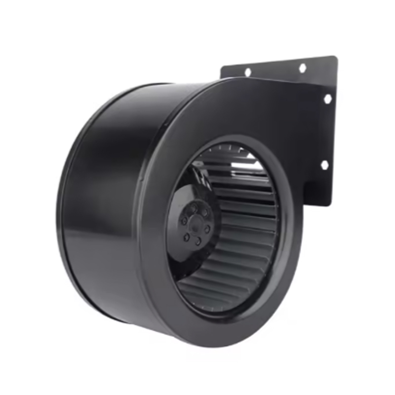
On most datasheets, 75 refers to the outer diameter of the impeller in millimetres. The forward-curved wheel sits inside a scroll housing, and the housing, not the wheel, defines the mounting footprint, the inlet ring and the outlet flange. Two fans both sold as 75mm can have completely different hole patterns.
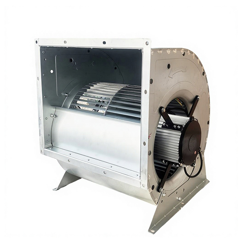
Series naming follows the same logic. A frame such as lkz-75/150W pairs a 75-class impeller with a 150W motor, which is why matching a drawing to a catalogue page by diameter alone usually ends in an adapter plate and lost weeks.
 LKZ 7-5-150W AC Centrifugal Blower FanCheck this galvanized-steel AC centrifugal blower for pressure-driven ventilation, with forward-curved impeller and published airflow, pressure, current, and speed data.View Product →
Before comparing airflow figures, confirm these fields in the order buyers normally check them.
| Specification field | What to confirm | Why it matters |
|---|---|---|
| Impeller diameter | Wheel outer diameter and width | Sets the achievable pressure and airflow envelope |
| Housing and footprint | Scroll outline, hole spacing, screw size | Determines drop-in fit; rarely interchangeable between suppliers |
| Inlet and outlet | Inlet ring diameter, outlet flange size and angle | Drives duct adapters and connection losses |
| Motor type | Single-phase AC, EC brushless, rated voltage | Decides speed control method and part-load efficiency |
| Power and speed | Watts at the rated point, speed range | Links electrical load, heat rise and noise |
| Air performance | Airflow and static pressure at one stated point | Only useful when your duty point sits on that curve |
| Interface | Lead length, connector, 0-10V or PWM input | Affects installation cost and controllability |
Where the 75mm Blower Class Earns Its Place
Compact blowers in this size class appear wherever air must be pushed through something rather than simply stirred. Four duty patterns cover most of the enquiries we receive.
Spot cooling inside instruments and enclosures
A 75mm blower ducted to a heat sink or power module produces a narrow, high-velocity jet at the component that runs hot. The scroll outlet aims that stream, while an axial fan spreads air in every direction and loses much of it against the chassis walls.
Air circulation in purifiers, dehumidifiers and appliances
Filter media, carbon beds, condensers and evaporator coils typically add resistance well beyond the reach of a 75mm axial fan, yet still inside the range of a forward-curved wheel. This is classic mini centrifugal fan duty in air purifiers, dehumidifiers and heating appliances.
Duct boosting and shallow HVAC terminals
Small scroll blowers also serve as booster stages in narrow duct runs, fan-coil terminals and VAV boxes where the fan box has to stay shallow. Because the outlet is directional, duct transitions are shorter and exit losses are lower.
Replacing axial fans as back pressure rises
As a working rule, once system resistance passes roughly 50 to 60 Pa, a centrifugal wheel of the same diameter moves more air than an axial fan of that size, and the gap widens quickly above 100 Pa.
AC or EC Drive: the Choice That Sets Controllability
The 75mm class offers two drive families, and the decision is usually about control rather than price.
Single-phase AC with capacitor run
A single-phase AC motor is direct-driven, simple and the least expensive option. Speed follows supply frequency and pole count, so the same fan behaves differently on a 50Hz and a 60Hz supply. Variable speed through external voltage regulation is imprecise, load-dependent and often audibly rough.
EC brushless with 0-10V or PWM
An EC motor holds the commanded speed as filters load up, starts softly and draws less power at part load. We explain the underlying technology in our article on what EC centrifugal fans are.
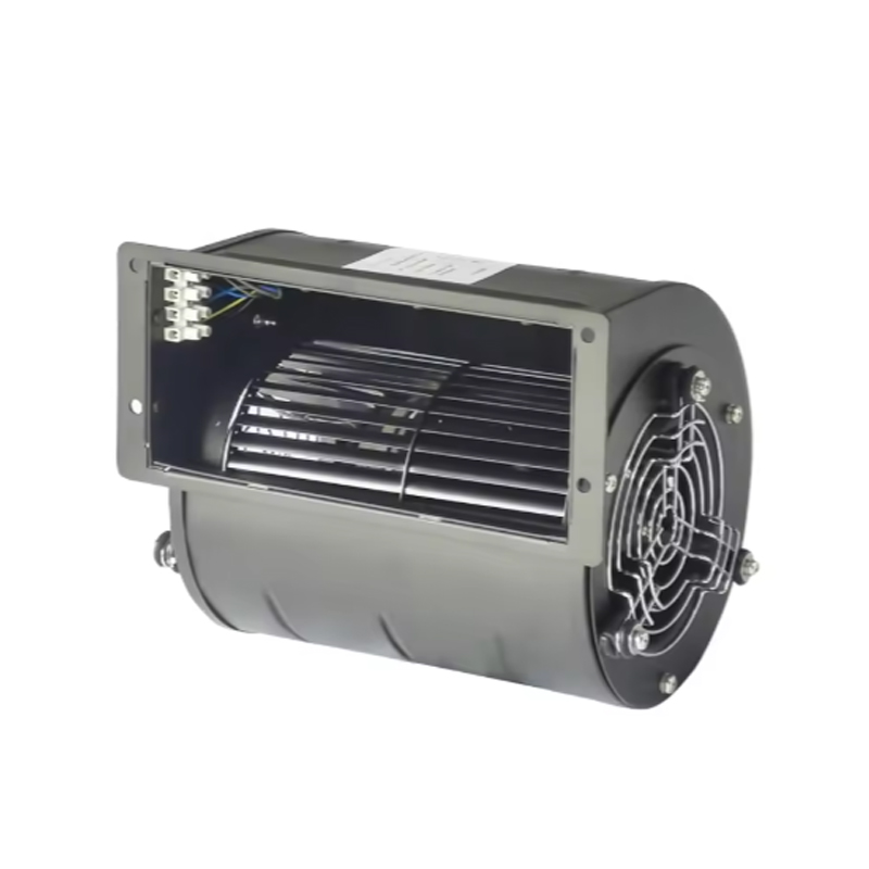
On our EC list, the 75 frame appears as the syz-75 low-pressure blowing unit. Higher static pressure duties in the same diameter usually move to forward-curved AC wheels or up to the next frame size, and it is worth knowing that before a design is frozen.
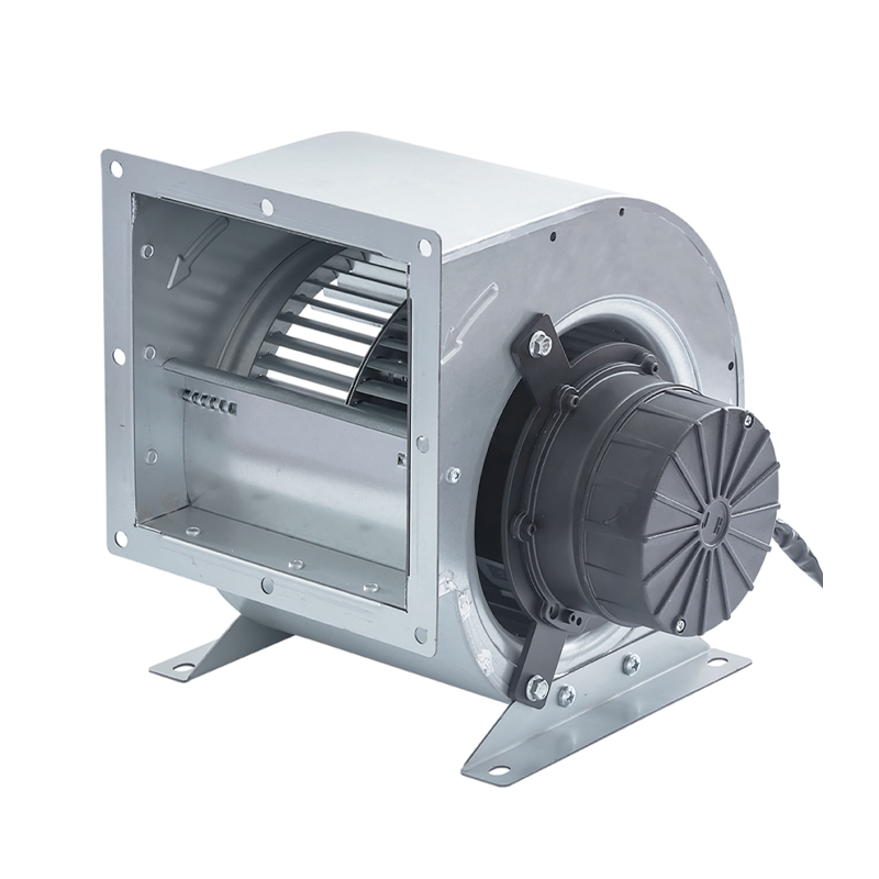 SYZ 7-5 Low-Pressure EC Centrifugal FanLow-pressure EC fan with plastic forward-curved impeller and 0–10 V/PWM speed control for variable-air-volume, HVACR, fresh-air, and air-purification systems.View Product →
EC is not automatically the right answer. Where an appliance runs at one fixed speed and cost pressure is real, a capacitor-run AC blower remains the cheapest way to push air through a filter.
Sizing a 75mm Fan Against the System Curve
A published airflow figure is measured at one stated static pressure. Free-air numbers look impressive and mean little once a filter sits in the path, because system resistance rises roughly with the square of airflow. The only figure that matters is the intersection of the fan curve with the system curve, known as the operating point.
- Fix the required airflow at the real operating condition, not at the start of life. A filter that loads up can add 30 to 50 percent resistance before replacement.
- Add up the losses: filter media, fin density, duct length, bends, grilles, and the inlet and outlet losses at the fan itself.
- Plot the system curve against the fan curve and check that the intersection sits in the middle third of the curve, not at either edge.
- Keep 15 to 25 percent airflow margin for manufacturing tolerance, altitude and dust.
- Check motor heating at that exact point. At low flow and high pressure the wheel churns the same air, and a small motor can run far hotter than its free-air rating suggests.
- Prototype with the real filter and the real duct. A bench test on an open frame says very little about installed behaviour.
Two installation details deserve early attention. Inlet clearance matters more than most drawings allow, since restricting the inlet ring to about 20mm of open space costs both airflow and noise. The outlet angle, meanwhile, can usually be set at the design stage, so choose the scroll orientation before the sheet metal is cut.
Where 75mm Specifications Go Wrong
Failures in this size class repeat in four patterns:
- Sizing on free-air airflow instead of the installed operating point, so a blower that performs on the bench stalls against a dense filter.
- Leaving no inlet clearance. A 75mm wheel pulls air from a hemisphere, and a flat wall close to the inlet ring cuts flow while raising noise.
- Assuming AC and EC versions share a curve. Motor slip, control electronics and speed limits shift the operating point, so performance must be re-verified when the drive changes.
- Ignoring rotation direction and outlet orientation until the prototype stage. A mirrored scroll housing is a new tool, not a drawing note.
Because the interface is the real risk, ask for three documents before a first order: a dimensional drawing with hole spacing and tolerances, a fan curve that states its measurement conditions, and a sample for a fit check. If bearing type, insulation class or expected service life is missing from the datasheet, treat that specification as unverified until it is in writing.
75mm Centrifugal Fan FAQ
Can a 75mm centrifugal fan replace a 92mm axial fan?
Usually yes, when system resistance is the problem. The centrifugal unit is smaller but generates higher pressure, so a ducted 75mm blower typically outperforms a 92mm axial fan once resistance passes roughly 50 Pa. The trade-offs are a narrower airflow spread and a more directional noise pattern.
How much static pressure can a 75mm blower produce?
It depends on wheel design, motor power and speed. Forward-curved wheels in this size are built for volume at moderate pressure, while higher-speed radial designs trade airflow for pressure. Never accept a single pressure number; ask for the full curve and the speed at which it was measured.
Do 75mm centrifugal fans come in DC versions?
Yes. This frame class exists with AC single-phase, EC and low-voltage DC motors. The drive decides the control interface, so specify voltage, control signal and required speed range before requesting a quotation.
How long does a 75mm fan last?
Bearing system, ambient temperature and running speed decide that, not the diameter. Sleeve bearings suit clean, moderate-temperature duty, while ball bearings cost more and tolerate higher speed and heat. Ask for the bearing type and a rated life figure at your duty point.
Choose the Duty Point, Then Confirm the Fit
A 75mm centrifugal fan works when it is selected for the resistance it has to beat: filter pressure drop, duct losses and the airflow your thermal design needs at the end of the filter's life. Confirm impeller diameter and footprint against your drawing, pick the drive that matches how airflow will be controlled, and verify the operating point on a real prototype.
If you are weighing AC against EC, or want a straight answer on whether the 75 frame is enough for your duty, send us your airflow and static pressure targets along with the space you have available, and we will tell you which frame and wheel form fits.

 ENG
